An ultra low power radio is not a current number. It is a timeline.
A sensor wakes, samples, encrypts, transmits, waits for acknowledgements, perhaps retries, then returns to sleep. Battery life depends on the area under that current trace and on everything the device does between useful events. A low receive current can be defeated by long connection windows. A larger transmit peak can be cheaper when the exchange finishes sooner.
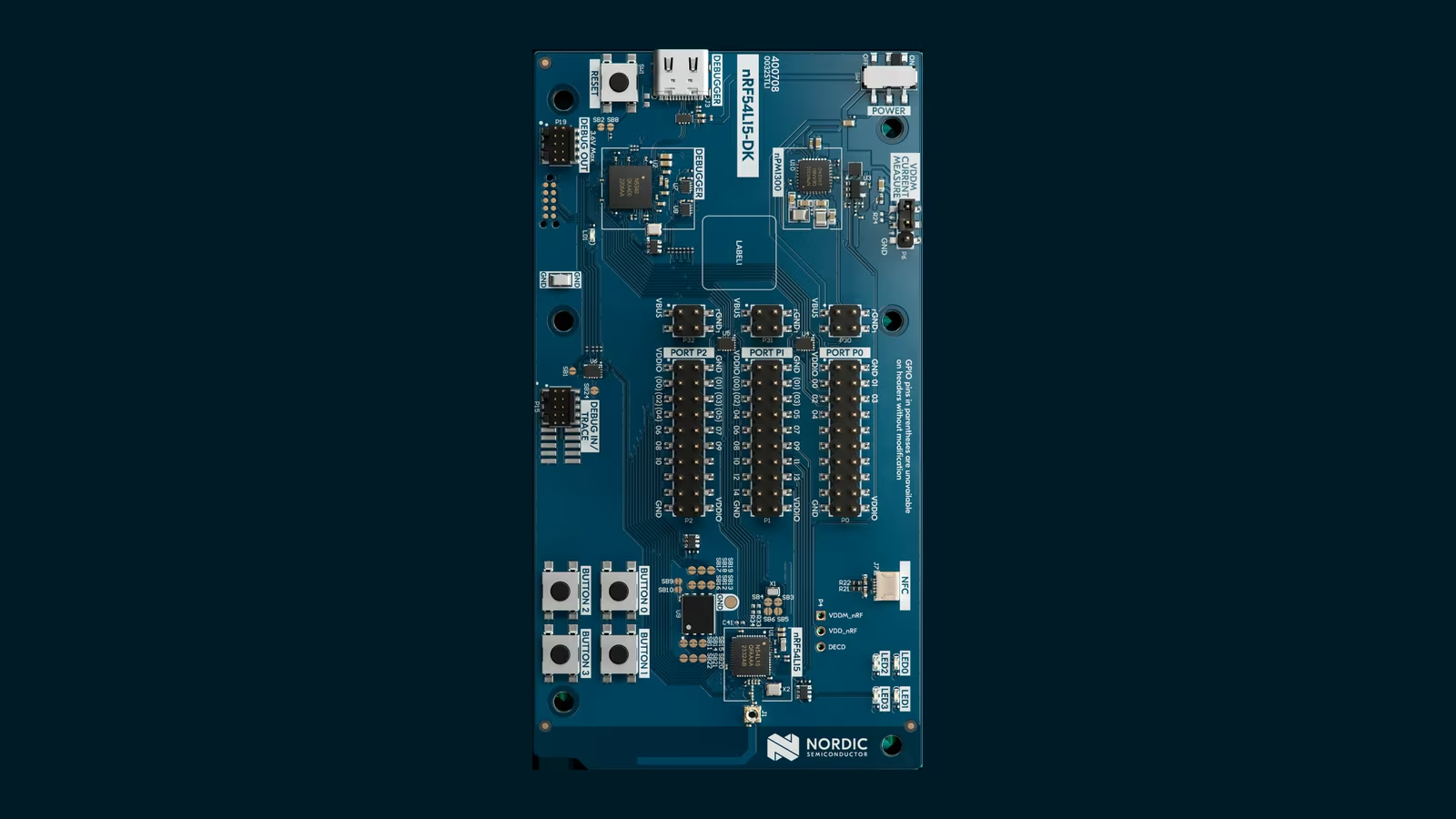
The Nordic nRF54L15 Development Kit is good because it makes that system visible. It combines a current Nordic multiprotocol SoC, onboard debugging, accessible power measurement points, external flash and an SDK with Matter and Thread samples. It can also emulate the smaller nRF54L10 and nRF54L05 variants.
The board is not a battery product and cannot tell us final life by itself. It is a disciplined place to turn architecture assumptions into traces before a custom PCB makes them expensive.
The nRF54L15 is a platform decision
Nordic’s nRF54L15 product page lists a 128 MHz Arm Cortex-M33, 1.5 MB of nonvolatile memory and 256 KB RAM. It supports Bluetooth LE, Thread, Matter, Zigbee, Bluetooth Channel Sounding, Amazon Sidewalk, Aliro and proprietary 2.4 GHz modes.
The radio supports IEEE 802.15.4 at 250 kbps for Thread and Zigbee, plus Bluetooth LE and proprietary modes. The maximum documented transmit power depends on package, while the product specification lists receive sensitivity down to minus 102 dBm for IEEE 802.15.4 under its stated conditions.
The architecture also includes a RISC-V coprocessor, security hardware, TrustZone, secure boot and tamper related functions. Those are valuable building blocks, not a finished security model. Product firmware still has to define key provisioning, update policy, debug locking, rollback protection and failure handling.
The pin compatible nRF54L10 and nRF54L05 options create a possible cost and memory ladder. The DK can emulate them, which lets a team discover whether the application genuinely needs the L15 resources before committing a bill of materials.
That emulation is one of the board’s strongest commercial features. Memory requirements tend to grow during Matter development through additional clusters, certificates, logging and update slots. Starting on the largest option is comfortable. Testing the smaller target early shows whether that comfort has a unit cost.
The DK exposes the right development surfaces
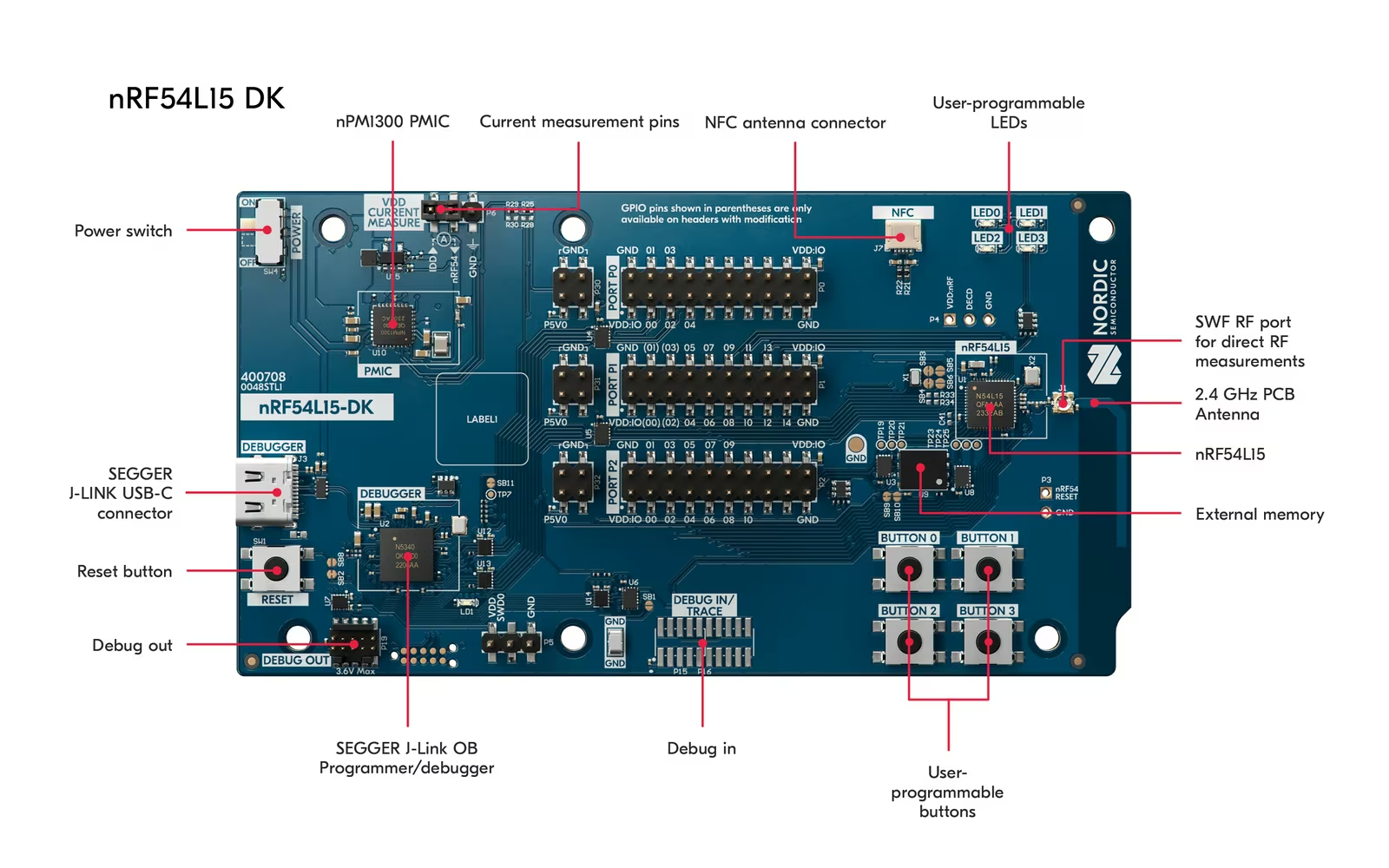
The official nRF54L15 DK documentation lists the nRF54L15 SoC, 2.4 GHz and NFC antennas, an SWF connector for direct RF work, four user buttons, four LEDs, a SEGGER J-Link onboard debugger, two virtual serial ports, power measurement pins and 8 MB external flash.
Related reading
Headers expose GPIO and peripheral interfaces. The board’s nPM1300 power management circuit can supply the SoC from 1.8 to 3.3 V. Current documentation notes a default 1.8 V supply and provides ways to separate or programmatically disconnect extended DK functions.
This is exactly what a development kit should do. It reduces friction during firmware work while making it possible to remove the convenience circuitry from a power measurement.
The convenience can also distort results. LEDs, debug traffic, external flash, serial bridges and the onboard debugger do not belong in every final device. A trace taken from the USB input measures the development board system, not necessarily the application SoC rail.
Nordic provides a dedicated P6 measurement point for VDD:nRF. Use the current hardware revision instructions because solder bridge and power details have changed across prerelease and production board revisions.
nRF Connect SDK is capable and substantial
The nRF54L15 DK is supported in nRF Connect SDK, Nordic’s Zephyr based environment for its wireless families. The toolchain includes configuration, builds, programming, debugging, protocol samples and integration with VS Code or command line workflows.
For a developer already using Zephyr, this is a mature path. Devicetree, Kconfig, west workspaces and structured board targets make hardware variants reproducible. For someone coming from a small Arduino sketch, the first build can feel like learning an operating system because that is largely what is happening.
Pin the SDK version for a project. Record the toolchain, board revision, sample commit and configuration fragments. Matter and Thread stacks evolve, and a successful build against latest is not a reproducible product baseline.
Start from the smallest official sample that exercises the needed path. Build and flash a plain Thread or Bluetooth example before a full Matter accessory. Then add application behaviour. When commissioning fails, this separation tells you whether the radio network, Matter fabric, cluster implementation or product logic is responsible.
Keep serial logging useful but conditional. Logging can prevent deep sleep, extend wake time and change timing. A production power profile with verbose debug enabled is a measurement of the logger.
Matter over Thread is more than one radio exchange
A Matter sensor on Thread must maintain network participation, secure sessions and application state. Commissioning uses Bluetooth LE for the initial rendezvous in common flows, then transfers credentials for the operational IP network. Normal commands travel through Thread.
This creates several energy classes: commissioning, steady idle, periodic child updates, application reports, secure session work, retries and firmware updates. One average number hides them.
Measure commissioning separately because it is intense but rare. Measure a normal report from settled idle through return to the same idle state. Then leave the device connected long enough to capture maintenance traffic it did not initiate.
Thread device role matters. A Sleepy End Device can spend much of its time asleep and poll its parent. A router capable device remains more available and consumes a different budget. A battery product should not be measured in a role it will not use.
Matter subscription intervals also matter. An overly eager controller or application configuration can cause more reports than the sensor’s physical value justifies. Optimising radio current while sending redundant state is engineering the wrong layer.
The meaningful unit is charge per event
Nordic’s measurement guide supports the Power Profiler Kit II, oscilloscope, ammeter or power analyser. PPK2 is especially convenient because it can power the target and record a wide current range over time.
For one application event, integrate current from the settled sleep baseline through wake, sensor work, radio exchange and return to baseline. The integral is charge, often expressed in microcoulombs or microamp hours. Repeat enough events to expose variation and retries.
Record supply voltage, firmware commit, network role, transmit power, logging state, payload, report interval and radio conditions. Without them, the number cannot be compared.
Use a digital marker or spare GPIO around the application phase if possible. PPK2 digital inputs can align firmware events with the current trace. That turns a broad peak into a sequence that can be optimized.
Nordic warns that an open virtual serial port can introduce noise into current readings. Close the terminal for the final capture. Also isolate unused DK hardware according to the current manual rather than assuming the measurement header removes every peripheral automatically.
Do not copy a result from a development kit into a battery life claim. The custom board, regulator, sensors, pull resistors and leakage paths will change it. The DK measurement validates firmware architecture and establishes a baseline.
Related reading
A battery model needs more than nominal capacity
A basic model adds sleep consumption to the charge of each event:
daily charge = sleep current x time asleep + sum of event charge x event count
That is the beginning. Real cells have self discharge, temperature dependence, voltage curves, internal resistance and capacity that changes with load. Coin cells are especially sensitive to radio peaks as they age.
Use the target cell’s manufacturer curves at the expected pulse load and temperature. Include the regulator’s quiescent current and efficiency. Set a conservative usable capacity rather than dividing by the largest number printed on the cell.
Retries deserve their own scenario. Run the device near the edge of reliable Thread coverage or introduce controlled attenuation. One successful lab exchange can be far cheaper than behaviour in a metal enclosure at the end of the mesh.
Model firmware updates separately. A large download, flash writes and verification may consume a noticeable portion of a small battery. That can still be acceptable if updates are rare and necessary, but it should be budgeted.
Finally, validate with real cells over time. A profiler can replay load patterns or help derive them, but ageing and chemistry belong in the test plan.
Radio performance must be tested in the final enclosure
The DK provides a PCB antenna and SWF RF connector. It is excellent for software development and conducted radio measurements. It is not the antenna geometry of the final sensor.
A plastic enclosure, ground plane, battery, display cable and nearby wall can detune or shadow the antenna. A conducted sensitivity or output measurement confirms the radio path to the connector. Over the air range confirms the full product.
Use the intended transmit power and regulatory domain. Higher output can improve a marginal link while increasing current and potentially changing compliance requirements. A good antenna often saves more energy than a firmware level increase because it reduces retries in both directions.
Thread also depends on the surrounding 2.4 GHz environment. Wi-Fi, Bluetooth and neighbouring networks share spectrum. Test coexistence with the home’s access point active and under load.
The nRF54L15’s protocol breadth is valuable, but simultaneous requirements need architecture. A product using Bluetooth for commissioning, Thread for operation and another 2.4 GHz function still has one radio scheduling shared work.
Security features need a provisioning story
The SoC includes Arm TrustZone, secure boot, secure storage support, cryptographic acceleration and physical protection functions. These features can establish a strong root of trust.
They only help when production defines ownership. Where are device attestation credentials injected? Who can sign firmware? Can an older vulnerable image be installed? Is debug access locked, recoverable or permanently disabled? What happens to a returned device?
Matter certification and protocol conformance do not answer the whole product threat model. Network credentials, application data, factory interfaces and cloud administration may sit outside Matter.
Use development keys only in development. Separate manufacturing secrets from the source repository and CI logs. Plan certificate rotation, secure update and factory reset before the prototype is handed to another team.
The DK makes security code accessible, but it also makes debug easy. That is correct for development and deliberately different from a shipping configuration.
Migration from nRF52 or nRF53 should be evidence based
The nRF54L15 offers more processing performance, modern security and a new memory architecture. It is tempting to treat it as a faster replacement for an nRF52840 or nRF5340 design.
Software compatibility through the SDK helps, but peripheral details, power states, package layout and timing still require review. Build the real application, not only a vendor sample. Check flash and RAM maps, interrupt timing, radio coexistence and bootloader assumptions.
Measure the same representative workload on both platforms with comparable voltage and radio settings. Compare energy per completed task, not only average current. A faster core may finish and sleep sooner even with a larger active current.
The smaller nRF54L10 and L05 variants can reduce cost when memory permits. Emulate them on the L15 DK early, then confirm on actual silicon and production package before release.
Related reading

A good evaluation ends with production criteria
Before the DK leaves the lab, convert what it taught into gates for the custom board. Set budgets for sleep current, event charge, radio retries, boot time, update energy and memory headroom. Attach the firmware commit and measurement procedure to each limit.
Repeat the same scenarios on the first production prototype. Differences are expected because the power tree, antenna and sensors have changed. Unexplained differences are not acceptable simply because the device still works.
Keep one DK as a reference platform. When a later SDK or protocol update changes consumption, run the old and new firmware on identical hardware. That separates a software regression from board variation and makes long term maintenance far less speculative.
Cost is the engineering time it prevents
Nordic sells the nRF54L15 DK through distributors, so local price and stock vary. The board should be evaluated alongside a PPK2, debug accessories, prototype sensors and engineer time rather than as a standalone gadget.
Its value is high when one board replaces separate programmers, breakouts and uncertain power hacks. Onboard J-Link, current measurement support, radio connectors and official examples shorten the path to a defensible prototype.
It is unnecessary for someone who only wants to operate Matter devices at home. This is product development hardware. A USB dongle or finished controller is a better tool for network administration.
Verdict
The nRF54L15 DK is a strong development platform for teams building low power Bluetooth, Thread, Matter or Zigbee products. It exposes debugging, RF and power measurement cleanly enough to investigate the complete event timeline before a custom PCB makes mistakes expensive.
Its data sheet figures are a starting point. Final battery life depends on firmware state, network role, retries, regulator, enclosure and cell, and the DK cannot give that number by itself.
Why I recommend it
- Generous, current silicon. The SoC has a 128 MHz Arm Cortex-M33, 1.5 MB of nonvolatile memory and 256 KB RAM, with Bluetooth LE, Thread, Matter, Zigbee and proprietary 2.4 GHz modes.
- A cost ladder to test early. The DK can emulate the pin compatible nRF54L10 and nRF54L05, so a team learns whether it genuinely needs L15 resources before committing a bill of materials.
- One board instead of a pile of hacks. Onboard SEGGER J-Link, an SWF connector for conducted RF work and a dedicated P6 measurement point for VDD:nRF replace separate programmers, breakouts and uncertain power hacks.
- Made for charge per event. PPK2 digital inputs can align firmware events with the current trace, turning a broad peak into a sequence that can be optimized.
- A security foundation. TrustZone, secure boot, cryptographic acceleration and physical protection functions can establish a strong root of trust.
Why it may not be for you
- Zephyr is a lot to learn. For someone coming from an Arduino sketch, the first nRF Connect SDK build can feel like learning an operating system, and evolving Matter and Thread stacks mean every version has to be pinned.
- Convenience distorts measurements. LEDs, debug traffic, external flash and an open virtual serial port all affect a trace, and solder bridge details have changed between board revisions.
- Security is building blocks only. Key provisioning, firmware signing, rollback protection and debug locking are still the product team’s work.
- The board is not the whole bill. Price and stock vary by distributor, and it should be costed with a PPK2, debug accessories, prototype sensors and engineer time.
I would choose the DK when a project needs current Nordic silicon, Matter over Thread, systematic energy work or a path across L15, L10 and L05, and I would connect a PPK2 before optimizing code. Someone who only wants to operate Matter devices at home should use a USB dongle or a finished controller. If a project is not prepared to do the measurement and configuration work, the headline low power numbers will not save it.
Product images: Nordic Semiconductor.
One email a month: new articles, reviews and the upcoming live webinar + free recording. No spam, unsubscribe anytime.